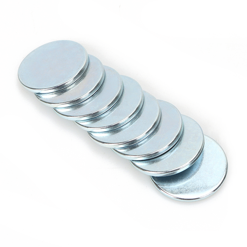
Modern motor and sensor designs face relentless performance pressure in 2026. Engineers must achieve unprecedented miniaturization while surviving extreme thermal environments. You cannot compromise on magnetic stability under these severe conditions. Specifying a radially magnetized ring represents a critical engineering decision. It involves complex yield variables and intense manufacturing considerations. A simple geometric miscalculation can ruin an entire production run. We prepared this guide as a dedicated technical briefing for engineering and procurement teams. You will discover how to evaluate material limits accurately. We will explore manufacturing realities and examine critical vendor capabilities. Before finalizing your component specifications, read this framework carefully. It provides the exact parameters you need to succeed.
Key Takeaways
Thermal Ceiling: N35SH guarantees stability up to 150°C, prioritizing high intrinsic coercivity (Hcj) over maximum energy product (BHmax) to prevent irreversible demagnetization in high-stress environments.
Manufacturing Constraints: True radial magnetization requires specialized orientation fields during pressing; it carries higher initial tooling costs and tighter geometric limitations compared to diametrical or axial options.
Application Sweet Spot: The N35SH radial combination is optimal for compact, high-RPM BLDC motors and precision Hall-effect sensors requiring continuous, seamless magnetic flux transitions.
Sourcing Risk: Procurement success hinges on validating a supplier’s BH curve data across temperature spectrums and their ability to maintain flux consistency across production batches.
Analyzing N35SH Material Properties and Thermal Performance
Baseline Grade Comparison
Standard N35 neodymium provides excellent magnetic strength at room temperature. It fails quickly under continuous high-heat loads. Ultra-high-temperature grades like UH or EH survive extreme heat easily. However, they often sacrifice overall magnetic remanence. N35SH occupies a vital middle ground for modern engineering. The "35" rating indicates the maximum energy product (MGOe). The "SH" designation signifies a Super High thermal rating. Engineers accept a slight MGOe trade-off here. This compromise guarantees an intrinsic coercivity (Hcj) of at least 20 kOe. It prevents permanent failure in hot operating environments. High-speed rotors generate intense eddy currents. These currents create significant internal heat. The SH grade absorbs this thermal shock effectively.
Neodymium Grade
Max Energy Product (BHmax)
Intrinsic Coercivity (Hcj)
Max Operating Temp
Standard N35
33-36 MGOe
≥ 12 kOe
80°C
N35SH
33-36 MGOe
≥ 20 kOe
150°C
N35UH
33-36 MGOe
≥ 25 kOe
180°C
BH Curve Realities
Demagnetization curves behave distinctly under active loads. At 100°C, the N35SH curve remains relatively linear. Once you approach 150°C, the curve develops a prominent "knee" in its lower quadrant. Operating past this thermal threshold invites disaster. You risk irreversible flux loss. This happens frequently if you lack a proper permeance coefficient (Pc) design. A low permeance coefficient accelerates thermal degradation. Engineers must calculate the exact magnetic circuit dynamics. You must ensure the operating point stays above the curve's knee. External demagnetizing fields push this operating point lower. Stator coil currents act as external demagnetizing forces. You must account for these forces during the simulation phase.
Data Verification
Theoretical room-temperature datasheets hold little value for intense applications. You must demand modern laboratory test reports. Look for 2026-standard third-party validations. These reports must confirm magnetic flux consistency at maximum operating temperatures. Never assume your components will perform linearly without empirical proof. Ask vendors for actual hysteresis graphs at 150°C. Review the open-circuit flux measurements carefully. Trusting generic marketing data leads to premature motor failure. Insist on raw testing data from certified magnetic laboratories. A reliable Radial Magnetization N35SH Magnet always comes with comprehensive thermal validation documents.
The Complexity of Radial Magnetization: Process and Feasibility
Production Mechanics
True radial magnetization demands complex anisotropic alignment. Manufacturers must orient microscopic magnetic domains outward from the center. They achieve this alignment entirely during the powder pressing stage. Specialized water-cooled orientation coils generate immense electromagnetic fields. These fields push the powder domains into a continuous radial pattern before sintering. This creates a perfectly seamless magnetic field. It differs vastly from simple axial or diametrical pressing. The required equipment operates at extreme voltage levels. The pressing process requires absolute precision. Even slight deviations in the magnetic alignment field ruin the anisotropic structure. The resulting ring possesses exceptional radial strength.
Yield and Geometric Risks
Manufacturing thin-walled radial rings introduces massive yield risks. Sintering radially aligned powder creates uneven internal stresses. The material shrinks differently across various axes. This anisotropic shrinkage often leads to warping. Machining these fragile rings back into tolerance risks catastrophic cracking. You must establish viable baseline dimensions early in your design. We recommend strict minimum wall thickness guidelines. A wall thinner than 2mm usually results in unacceptable scrap rates. Keep your geometries robust. Avoid aggressive chamfers or thin flanges.
Common manufacturing pitfalls include:
Micro-fractures developing during the final diamond grinding phase.
Uneven flux density caused by poorly wound alignment coils.
Deformation during the high-temperature sintering cycle.
Coating buildup on ultra-tight inner diameter tolerances.
Radial vs. Approximated Multipole
You might consider using multi-segment glued assemblies instead. They approximate a radial field using individual diametrically magnetized pieces. Glued assemblies avoid complex pressing coils. However, they introduce physical seams. They suffer from inconsistent flux transitions at every glue joint. A true continuous radial ring delivers flawless magnetic waves. It improves motor efficiency significantly. It eliminates the risk of adhesive failure at 150°C. The performance delta usually justifies the complex manufacturing process. True radial rings provide perfectly symmetrical sinusoidal waveforms. This symmetry remains impossible to achieve with glued rectangular segments.
Designing for Application: When to Spec a Radial Magnetization N35SH Magnet
Precision Sensors
High-resolution rotary sensors require flawless signal fidelity. Consider strict 8x8mm dimensional constraints. Multi-pole alternatives often create magnetic "dead zones" at segment joints. The sensor reads erratic values when passing these physical gaps. A continuous radial flux eliminates these dead zones entirely. The Hall-effect sensor reads a perfectly smooth magnetic sine wave. This ensures absolute positional precision. Engineers building modern robotic joints rely on this accuracy. Any signal jitter degrades the entire control loop. Using a Radial Magnetization N35SH Magnet guarantees clean analog or digital encoder outputs. It provides the seamless transitions required for absolute encoders.
High-Efficiency Rotors
Servo motors and Electric Power Steering (EPS) systems benefit immensely from continuous radial fields. These rings allow for exceptionally tight air gaps between the rotor and stator. Tight air gaps increase torque density dramatically. Continuous radial fields also reduce cogging torque. Cogging torque causes unwanted vibration and audible noise. Eliminating it ensures smooth rotation. This proves crucial for modern automotive steering applications. Drivers demand seamless steering feedback. A radially magnetized ring delivers that smooth experience. It maximizes the power-to-weight ratio for aerospace actuators as well. The thermal stability of the SH grade ensures the rotor survives high-load torque spikes.
Surface Treatment Strategies
High heat and continuous rotation demand careful coating selection. You must protect the neodymium from rapid oxidation. You must evaluate plating options suitable for 150°C environments.
NiCuNi (Nickel-Copper-Nickel): This triple-layer plating offers excellent corrosion resistance. It survives high temperatures flawlessly. It remains the industry standard for most motor applications.
Zinc Plating: Zinc suits less aggressive environments. It applies thinly but offers lower maximum temperature stability. It degrades faster in highly humid conditions.
High-Temp Epoxy: Epoxy works beautifully up to 150°C. It provides exceptional resistance to salt spray and chemicals. However, it requires a thicker application layer.
You must account for coating thickness in your final design. A standard NiCuNi layer adds 10-25 microns per surface. This physical layer directly impacts the final air gap calculation. It slightly alters the overall magnetic field strength reaching the stator. Always specify your critical dimensions as "after plating".
Vendor Evaluation Framework for 2026
Tooling and Lead Times
Custom alignment coil creation requires extensive preparation. Set realistic expectations for your prototyping schedule. True radial magnets demand custom orientation coils for every specific dimension. You cannot simply cut them from a larger pre-magnetized block. Expect longer lead times for initial samples. Tooling design involves complex electromagnetic simulations. The vendor must machine custom pressing dies. They must wind specific copper orientation coils. This process takes several weeks. Factor this reality into your project timeline. Rushing the tooling phase guarantees poor magnetic alignment. Verify that your vendor possesses in-house tooling capabilities. Outsourced tooling often leads to quality control failures.
Shortlisting Criteria
You need a rigorous evaluation process for potential manufacturing partners. The 2026 manufacturing landscape demands absolute precision. Look for specific technical capabilities when reviewing supplier audits. Do not rely on visual inspections alone.
Quality Control Protocols: Does the vendor use 100% automated flux mapping? Manual testing cannot catch micro-deviations in the radial field. Ask for their Helmholtz coil testing procedures.
Material Traceability: Can they track the raw rare-earth material batch to the final sintered product? You need complete lot traceability. This ensures consistent dysprosium content across orders.
Tolerance Capabilities: What are their standard geometric and magnetic deviation guarantees? We expect ±5% flux density variance at most. Dimensional tolerances should hold ±0.05mm reliably.
Performance Justification Framework
You must weigh the engineering benefits against the manufacturing complexity. A single-piece radially magnetized ring delivers unmatched flux symmetry. It greatly simplifies your final assembly process. Compare this against a multi-piece segmented rotor. Segmented assemblies suffer from stacked tolerance errors. Workers must manually glue each segment. This introduces severe human error risks. If your application demands zero cogging and high RPM stability, the single-piece radial approach wins. Integrating a single Radial Magnetization N35SH Magnet reduces assembly line failure rates. It guarantees long-term thermal reliability. It justifies the intense upfront engineering effort.
Conclusion
A carefully specified continuous magnetic ring remains a highly effective solution for modern engineering. It dominates high-heat, tight-tolerance rotary applications. You must ensure your geometric design respects inherent manufacturing limits. Do not push wall thicknesses beyond material capabilities. Always design for the exact thermal loads you expect. Rely on the N35SH grade to survive 150°C environments without catastrophic demagnetization.
Take decisive action early in your design phase. Engage directly with a magnetics application engineer during your CAD development. Review your permeance coefficients thoroughly. Confirm all tooling feasibility before finalizing technical prints. Request a physical material sample test immediately to validate the magnetic waveform.
FAQ
Q: What is the practical operating temperature limit for an N35SH radial magnet?
A: The N35SH grade is officially rated for 150°C. However, the actual practical limit depends entirely on your specific magnet geometry. A low permeance coefficient lowers this threshold. External demagnetizing fields from nearby coils also reduce the effective temperature limit. Always simulate the full magnetic circuit.
Q: Why is tooling so extensive for radially magnetized NdFeB rings?
A: True radial magnetization requires custom-wound alignment coils. The manufacturer uses these coils to orient the magnetic domains during the powder pressing stage. Every unique dimension requires a specific coil and pressing die. You cannot simply machine radial rings from a standard pre-magnetized block.
Q: Does NiCuNi plating affect the magnetic performance of N35SH?
A: The nickel-copper-nickel plating itself remains weakly magnetic. However, the physical thickness of the NiCuNi layers—typically 10 to 25 microns—increases the effective air gap. You must account for this physical barrier in your flux calculations. It reduces the usable magnetic field slightly.
Q: Can a radial magnetization N35SH magnet be custom-shaped (e.g., stepped)?
A: We strongly advise against complex shapes. Machining steps or deep grooves into radially aligned sintered NdFeB risks severe structural integrity issues. The anisotropic nature of the material makes it brittle. Complex geometries cause massive scrap rates and unpredictable magnetic flux patterns.