Engineering high-performance applications demands precise material selection. Neodymium N52 magnets represent the highest commercially accessible grade of NdFeB technology available today. They pack extraordinary magnetic force into incredibly minimal volumes. However, specifying these components introduces a complex balancing act. You must maximize magnetic yield while carefully managing strict thermal limitations. Engineers also face inherent mechanical fragility and rigid product constraints. Selecting the wrong specification often leads to catastrophic failure in the field or an unnecessary drain on engineering resources. This guide provides rigorous technical specifications and exact operating thresholds to prevent such outcomes. You will learn how to interpret complex performance metrics accurately. We also offer a clear, actionable decision framework. This ensures you implement these powerful components correctly in sophisticated product engineering and industrial designs.
Key Takeaways
- Maximum Energy Product: N52 delivers a BHmax of 49.5–52 MGOe, representing the upper echelon of commercially viable magnetic strength.
- Thermal Limitations: Standard N52 degrades above 80°C (176°F); high-temperature applications require specialized variants (e.g., N52H, N52SH) or alternative grades.
- Mechanical Realities: High brittleness and poor natural corrosion resistance necessitate protective coatings (typically Ni-Cu-Ni) and careful assembly protocols.
- Selection Logic: N52 is strictly for footprint-constrained applications where volume/weight must be minimized without sacrificing magnetic force.
What Defines an N52 Neodymium Magnet?
These components originate from a highly specific rare-earth alloy. The fundamental composition relies on a Nd2Fe14B tetragonal crystal structure. This microscopic arrangement gives the material exceptional magnetic anisotropy. It heavily favors magnetization along one specific directional axis. Such structural alignment allows the material to store massive amounts of potential energy.
Understanding the standard nomenclature helps you make accurate engineering decisions. Industry standards break the name down into two distinct parts. You must evaluate both aspects before integrating them into a final product design.
- The "N" Designation: This letter represents a standard temperature tolerance profile. It indicates a Maximum Operating Temperature of exactly 80°C. You cannot exceed this baseline without consequences.
- The "52" Value: This number defines the Maximum Energy Product (BHmax). It measures total magnetic energy capacity in MegaGauss-Oersteds (MGOe). A value of 52 sits at the absolute top of the standard commercial spectrum.
Manufacturers create these components using a highly controlled sintered construction process. They mill raw alloy into a very fine powder. Next, they press it under a strong magnetic field to align the particles perfectly. Finally, they sinter the pressed blocks at high temperatures in a vacuum chamber. This specialized manufacturing baseline results in extremely high magnetic density. However, it also creates inherent material brittleness. You cannot bend or flex them. They act much more like fragile industrial ceramics than traditional pliable metals. Rough handling will always result in severe cracking.
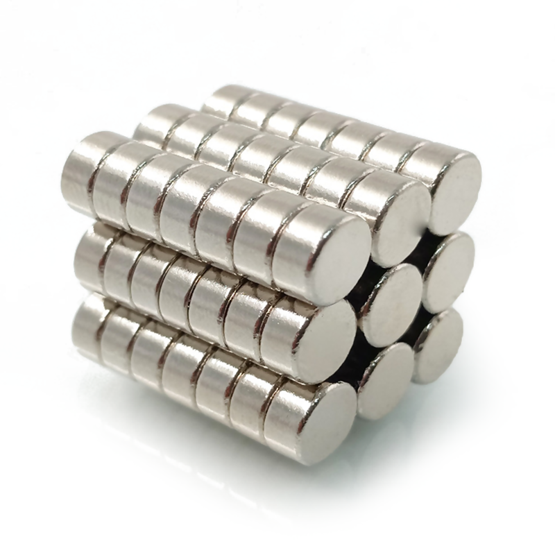
Core Technical Specifications and Magnetic Properties
Evaluating magnetic performance requires analyzing specific data points. We rely on four primary metrics to determine component suitability. You must weigh each criterion carefully to ensure operational success.
First, consider the Residual Magnetic Flux Density (Br). N52 grades consistently output between 14.3 and 14.8 kGs (1430–1480 mT). This value defines the absolute maximum magnetic flux the material can produce inside a closed circuit. It dictates the raw holding power available.
Second, examine the Coercive Force (Hcb). It measures ≥ 10.0 kOe (≥ 796 kA/m). This figure shows the basic resistance to demagnetization. It proves how well the component holds its charge under normal conditions.
Third, evaluate the Intrinsic Coercive Force (Hcj). Rated at ≥ 11.0 kOe (≥ 876 kA/m), this metric is critical. It dictates how well the material resists external demagnetizing fields. High opposing forces will not easily drain its energy.
Finally, review the Maximum Energy Product (BHmax). Ranging from 49.5 to 52.0 MGOe (394–414 kJ/m³), this serves as the primary indicator of total magnetic power. It represents the overall efficiency and strength of the unit.
| Performance Metric | Symbol | Value Range | Engineering Significance |
| Residual Magnetic Flux Density | Br | 14.3–14.8 kGs | Defines maximum potential magnetic flux output. |
| Coercive Force | Hcb | ≥ 10.0 kOe | Demonstrates base resistance to demagnetization. |
| Intrinsic Coercive Force | Hcj | ≥ 11.0 kOe | Shows resistance against external demagnetizing fields. |
| Maximum Energy Product | BHmax | 49.5–52.0 MGOe | Primary indicator of total concentrated magnetic power. |
Beyond magnetic output, you must account for specific physical and mechanical properties. The material features a dense structure, weighing approximately 7.4 to 7.5 g/cm³. It possesses a Vickers Hardness (Hv) of 570–600. This high hardness rating highlights a significant chipping risk during handling and assembly. Operators must use extreme caution on the assembly line. Rapid magnetic attraction often causes two pieces to snap together violently. They will shatter completely upon impact. We strongly recommend implementing automated assembly fixtures to prevent severe material damage.
Thermal Vulnerabilities and Operating Limits
Heat acts as the primary enemy of standard rare-earth components. You must carefully assess the thermal environment before final specification. Failure to do so guarantees premature system degradation.
The most critical implementation risk involves the Maximum Operating Temperature (Tw). Standard grades hit their absolute limit at 80°C (176°F). Exceeding this threshold causes irreversible flux loss. The magnetic field will not fully recover once the component cools down. The damage becomes permanent.
The Curie Temperature (Tc) sits at approximately 310°C (590°F). Reaching this extreme heat level results in complete and permanent loss of magnetization. The internal crystal structure loses all magnetic alignment. The component essentially becomes a dead piece of metal.
You also need to calculate reversible performance shifts. Performance fluctuates predictably as temperatures rise toward the 80°C limit. We use specific reversible temperature coefficients to predict these shifts:
- Alpha (Br) Coefficient: -0.12 %/°C. The flux density drops by this exact percentage for every single degree Celsius gained above ambient.
- Beta (Hcj) Coefficient: -0.60 %/°C. The resistance to demagnetization falls rapidly as ambient heat rises.
Risk mitigation must start early in the design phase. You must identify all environmental parameters prior to specification. Will the component sit near a hot motor winding? Is it exposed to direct, intense sunlight during operation? If your application ambient temperature frequently exceeds 75°C, using a standard grade presents a high failure risk. You need to pivot immediately to specialized high-temperature alternatives. Taking this proactive step ensures long-term operational reliability.
Surface Treatments and Corrosion Compliance
Bare NdFeB material oxidizes very rapidly in ambient humidity. The oxidation problem cannot be ignored. Uncoated components will degrade, rust, and eventually lose their structural integrity. They literally turn into a loose magnetic powder over time. To prevent this chemical breakdown, you must specify appropriate protective surface treatments.
We rely on several standard coating solutions to secure environmental compliance. Each option maps a specific feature to a desired outcome. Below is a detailed comparative chart outlining these primary solutions:
| Coating Type | Standard Thickness | Key Feature | Ideal Outcome / Application |
| Nickel-Copper-Nickel (Ni-Cu-Ni) | 15-21 microns | Industry standard triple-layer protection. | Provides good durability and moderate corrosion resistance for general use. |
| Zinc (Zn) | 8-15 microns | Highly economical single-layer application. | Serves perfectly for highly controlled, low-corrosion environments. |
| Epoxy Resin | 15-30 microns | Superior salt-spray resistance, fully non-conductive. | Ideal for demanding marine environments or fluid-exposed applications. |
Compliance and physical tolerances play a massive role in successful mechanical integration. Adding protective layers fundamentally changes the final outer dimensions. You must account for standard dimensional tolerances for coated parts. Suppliers typically offer ±0.1mm for standard industrial orders. You can request ±0.05mm for high-precision requirements. Always communicate these dimensional constraints clearly on your engineering drawings. The exact coating thickness must factor into your final CAD models. Failing to calculate this will cause severe assembly interference issues later.
Evaluation Framework: Is N52 the Right Grade for Your Project?
Deciding whether to use the highest available strength requires careful business problem framing. Sourcing these top-tier components commands premium resource investments. They are generally harder to source than standard N42 or N35 options. You must justify the specification logically.
You should specify this upper-echelon grade exclusively for constrained scenarios. Micro-electronics, intricate medical devices, and aerospace systems benefit greatly. In these advanced fields, extreme space and weight reduction fully justifies the investment. Miniaturization depends entirely on this maximized power density. High-torque precision motors also rely heavily on them. They require maximum flux across a very confined stator and rotor gap. They cannot function properly with weaker alternatives.
Sometimes, downgrading is the smarter engineering choice. You must consider alternative approaches to optimize your overall project. If physical space is not heavily constrained, redesigning the assembly makes perfect sense. Using a slightly larger N42 block achieves the exact same holding force. It offers higher thermal stability and simplifies your supply chain logistics. Additionally, if operating temperatures routinely exceed 80°C, a downgrade is mandatory. You must switch to a lower-grade high-temp variant. An N42SH easily withstands up to 150°C without permanent degradation.
Your shortlisting next steps should follow a strict evaluation protocol. Proceed methodically to avoid costly design errors. We recommend the following sequence:
- Request detailed B-H curve data sheets from qualified potential suppliers.
- Determine the exact magnet geometry required, such as specific disc, block, or ring shapes.
- Evaluate the environmental risks to confirm your coating requirements.
- Order small-batch prototypes to initiate physical field testing immediately.
Field testing these physical samples guarantees they meet your specific operational demands. It removes all theoretical guesswork from the engineering process.
Conclusion
We recognize this specific grade as the absolute apex of standard commercial NdFeB strength. It delivers unparalleled magnetic force for highly advanced engineering projects. However, you must carefully navigate the inherent technical trade-offs. The unmatched magnetic energy product always battles against strict thermal limits and mechanical brittleness. You cannot ignore these physical realities during the product design phase.
Take immediate action to validate your current component strategy. First, audit your operational temperature limits carefully. You must ensure they stay safely below the 80°C threshold. Next, review your assembly protocols to mitigate chipping and fracture risks effectively. Finally, consult directly with a magnetic engineering specialist. They can review your CAD files and confirm exact environmental conditions. Let them finalize your coating and tolerance specifications. Proactive validation prevents costly redesigns and guarantees long-term product reliability across all deployments.
FAQ
Q: How much stronger is an N52 magnet compared to N42?
A: The higher grade delivers a Maximum Energy Product about 20% greater than N42. This specification translates to roughly 15-20% more pull force in real-world scenarios. The exact performance increase depends heavily on your specific geometry and the characteristics of the target material.
Q: Are there Neodymium magnets stronger than N52?
A: N55 exists, but it is notoriously fragile. It remains highly sensitive to minor temperature variations. Because of these extreme limitations, it is not widely commercially viable for standard mass manufacturing. The grade 52 remains the practical maximum for reliable industrial applications.
Q: Can N52 magnets be machined or drilled?
A: No. Manufacturers build them using a sintered process, making them highly brittle. Machining destroys the protective coating immediately. It also poses a serious fire hazard due to pyrophoric dust. Drilling will completely shatter the piece. You must specify custom shapes before manufacturing begins.
Q: What is the lifespan of an N52 neodymium magnet?
A: Barring exposure to extreme heat, severe physical impacts, or heavy corrosion, they offer incredible longevity. The material will lose less than 1% of its total magnetic strength over a 10-year period. Proper surface coatings and strict environmental controls ensure this stable operational lifespan.