Integrating spherical magnets presents unique engineering challenges for modern product design. They create a highly concentrated point of contact on flat mating surfaces. They also introduce complex rolling dynamics in kinetic assemblies. You must manage these specific magnetic field shapes carefully during the design phase. Selecting the correct component goes well beyond simply picking the strongest magnetic grade available on the market. You must balance sheer magnetic output against strict physical dimensional tolerances. Engineers also need to account for environmental resistance and mandatory safety compliance. We provide a robust technical evaluation framework in this comprehensive guide. Product designers, mechanical engineers, and hardware buyers will learn to specify exact components for their operational requirements. You will discover how to match geometry, grade, and plating perfectly. This evaluation process ensures you avoid over-engineering parts while minimizing the risk of costly mechanical failure.
Key Takeaways
- Geometry dictates performance: The spherical shape focuses the magnetic field into a small point of contact, reducing overall shear strength compared to flat-faced magnets but enabling omnidirectional rotation.
- Grade and temperature go hand-in-hand: Higher neodymium grades (e.g., N52) offer maximum strength but often sacrifice maximum operating temperature thresholds.
- Coatings are not optional: Due to the high iron content in neodymium, specific platings (Ni-Cu-Ni, epoxy, gold) are required based on the application's exposure to moisture, friction, or chemicals.
- Compliance is critical: Consumer-facing applications must navigate strict regulatory limits regarding magnet size and pull force to prevent ingestion hazards.
1. Application Framing: When is a Ball Magnet the Right Choice?
Problem Framing
Spherical magnets stand apart fundamentally from traditional cylinders, discs, or blocks. Flat magnets maximize surface area contact against steel plates. They generate incredible shear resistance and boast massive static pull forces. However, they remain highly rigid and static. Spherical magnets behave entirely differently in application. They touch flat mating surfaces at a single microscopic point. This geometry naturally reduces their overall holding power significantly. Yet, they excel brilliantly in dynamic, moving applications. They allow smooth, multi-directional movement without breaking the magnetic circuit. You choose them when dynamic mobility matters far more than sheer static grip.
Success Criteria
How do you know if your implementation works effectively? You must define clear success parameters early in prototyping. We recommend evaluating your design against three primary operational goals:
- Frictionless Rotation: The sphere must pivot smoothly inside its machined socket without binding or excessive wear.
- Precise Sensor Triggering: The rolling action must deliver a consistent magnetic flux to activate external sensors reliably.
- Aesthetic Closure: Consumer devices demand a self-aligning, visually flawless fastening method that snaps together intuitively.
Common Technical Use Cases
- Magnetic Ball Joints: You can utilize the sphere for true 360-degree articulation. This works perfectly in robotic arms, camera mounts, or flexible lighting fixtures. The magnet acts simultaneously as both the rotating pivot and the retaining force.
- Sensor Triggers: Industrial automation relies heavily on these kinetic components. You can use rolling mechanics to activate Hall effect sensors in limit switches. The predictable axial magnetic field ensures highly accurate electrical switching.
- Precision Fastening: High-end consumer electronics use them frequently for detachable components. Premium jewelry clasps also benefit immensely from this design. The spherical shape guarantees a self-aligning closure every single time. It snaps together effortlessly without awkward visual misalignment.
2. Core Technical Specifications: Size, Grade, and Field Orientation
Sizing and Tolerances
The diameter directly dictates the total magnetic volume. A larger volume generates a significantly stronger holding force. Because volume calculates cubically, a tiny increase in diameter expands the magnetic mass drastically. Moving from a 4mm to a 5mm sphere nearly doubles the physical volume. You must calculate this expansion carefully to avoid overpowering delicate mechanical assemblies. Manufacturing tolerances matter immensely during this stage. Standard industrial tolerances sit firmly around ±0.05mm. You need precise tolerance control for press-fit housings. Precision-machined enclosures will jam immediately if the sphere arrives slightly oversized.
Selecting the Magnetic Grade (N35 vs. N52)
Engineers frequently face a critical structural trade-off. You must balance maximum magnetic strength against inherent material brittleness. An N52 grade offers the highest pull force commercially available today. However, higher neodymium grades increase the material's fragility drastically. We advise strongly against defaulting to N52 automatically. If a standard N35 grade meets your holding requirement, use it. Lower grades prove much more structurally stable under kinetic impact. They also offer a far more cost-effective solution for large-scale production runs. When integrating a Ball Magnet into a high-impact joint, choosing N35 prevents catastrophic chipping.
Magnetization Direction
You must understand exactly how the magnetic field flows. Almost all spherical magnets are magnetized axially. The magnetic axis runs perfectly straight through the center diameter. This orientation creates distinct north and south poles on opposite ends, much like the Earth. It dictates exactly how the spheres chain together. They form perfectly straight lines when connected pole-to-pole. This axial orientation also determines how they align automatically within mechanical housings. You must account for this polar behavior early during the CAD design phase. Ignoring polarity leads to repelling joints and failed assemblies.
3. Environmental Durability: Evaluating Coatings and Plating
The Necessity of Plating
Neodymium contains a massive amount of raw iron. It remains highly susceptible to rapid atmospheric oxidation. Without external protection, the material will rust, swell, and crumble away quickly. The outer coating acts as a vital structural necessity. It is never just an optional aesthetic choice. You must select a protective barrier matching your specific operational environment.
Comparing Standard Solutions
Table: Standard Coating Comparison for Spherical Magnets
| Coating Type | Primary Benefit | Ideal Application | Drawbacks |
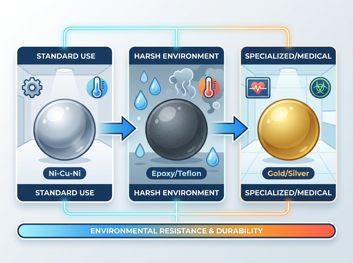
| Nickel-Copper-Nickel (Ni-Cu-Ni) | Excellent abrasion resistance, extremely smooth. | General engineering, dry rolling joints. | Not fully waterproof, contains nickel allergens. |
| Epoxy / Teflon | Superior chemical and moisture blocking. | Harsh environments, fluid exposure, medical tools. | Increases outer diameter, higher friction drag. |
| Gold / Silver | High biocompatibility, premium aesthetics. | High-end jewelry, specialized medical devices. | Very soft metal, prone to rapid mechanical wear. |
Nickel-Copper-Nickel is the undisputed industry standard. It provides a robust triple-layer defense. It also yields a remarkably smooth surface finish. This slickness benefits rolling kinetic applications perfectly. Epoxy or Teflon coatings serve completely different environmental needs. We recommend them heavily for harsh, corrosive atmospheres. They block fluid exposure effectively and provide a slight shock buffer. Note that polymer coatings increase the outer diameter slightly. You must adjust your socket tolerances accordingly. Gold or Silver platings handle niche consumer requirements. Medical device manufacturers specify them often for strict biocompatibility. However, these precious metals remain quite soft and wear away under friction.
Friction Considerations
Kinetic applications require careful, ongoing friction management. The chosen outer coating alters the coefficient of friction dramatically. Nickel slides effortlessly against most machined metals. Epoxy grips surrounding surfaces slightly more, potentially causing rotational drag. You must test the coated sphere against your specific housing material. This physical testing ensures smooth actuation throughout the product's entire expected lifespan.
4. Safety Standards, Compliance, and Implementation Risks
Thermal Degradation (Curie Temperature)
Heat destroys rare earth magnetic fields permanently. You face a severe risk of irreversible magnetic loss in hot environments. Standard N-series neodymium degrades rapidly once temperatures surpass 80°C (176°F). Once overheated past its limit, the material never regains its original holding strength. You must evaluate the operating environment's absolute maximum temperature. Specify high-temp material variants if needed. Grades ending in M (100°C), H (120°C), or SH (150°C) handle elevated temperatures safely. They sacrifice some base ambient strength to achieve this vital thermal stability.
Mechanical Vulnerabilities
We must address the harsh reality of mechanical chipping. Shattering represents a major operational hazard in kinetic designs. The point of physical impact concentrates entirely on a tiny curved surface. High-velocity collisions generate immense localized stress fractures. If two spheres snap together quickly across a gap, they frequently fracture on impact. You should incorporate dampening mechanisms inside your design. Try to limit the physical travel distance to prevent high-speed collisions. Incorporating a structurally sound Ball Magnet helps mitigate some risks, but hard design limits matter much more.
Regulatory Compliance
B2B and B2C brands face strict legal requirements globally. The Consumer Product Safety Commission (CPSC) enforces rigorous regulations. They closely monitor small, high-powered rare earth magnets to protect children. You must assess the "flux index" of your chosen components. This mathematical metric multiplies the magnetic flux density by the pole's surface area. Consumer applications must never violate ingestion hazard laws. If a sphere fits entirely inside a standard small parts test cylinder, it requires extreme caution. Its flux index must fall below the mandated legal threshold (typically 50 kG² mm²). Failing this vital compliance check results in mandatory, costly product recalls.
5. Supplier Evaluation and Shortlisting Criteria
Verifying Technical Claims
You must validate exactly what your material supplier promises. Always ask potential suppliers for detailed demagnetization curves. Engineers commonly refer to these as BH curves. They verify the stated magnetic grade and prove thermal stability. A legitimate manufacturer will provide this testing data happily. If they refuse or hesitate, you should look for another partner immediately.
Quality Assurance in Batch Runs
Operational consistency matters much more than peak performance. You should request comprehensive data on batch coating uniformity. Ask to see their recent salt spray test results. These tests usually run for 24 to 72 hours. This proves the plating can withstand environmental stress without blistering. Next, check for strict consistency in magnetic polarity alignment. Every single sphere must behave identically when dropped into your automated assembly line.
Custom vs. Off-the-Shelf
You face an important purchasing decision regarding sizing. We recommend buying standard metric sizes initially for all projects. Popular diameters like 5mm or 10mm remain readily available everywhere. They keep early prototyping costs extremely low. Tooling custom, non-standard diameters requires significant upfront investment. Only pursue custom sizes for highly proprietary housings. Do this only when standard metric sizes physically cannot fit your design parameters.
Next-Step Actions
Start small to minimize your initial financial risk. Order a highly limited sample batch first. Use this pilot batch to test the actual pull force physically. Verify the tight tolerance fit within your machined housing. Assess the true impact resistance in the actual prototyping environment. Complete these rigorous, real-world tests before committing capital to full-scale procurement.
Conclusion
You must approach the selection process strategically to avoid component failure. Start your project with a clear, logical evaluation funnel.
- Define your hard dimensional limits first. Measure the exact housing cavity to determine maximum diameter and required tolerances.
- Establish regulatory constraints immediately. Calculate the maximum allowable flux index if designing consumer-facing goods.
- Select the lowest functional magnetic grade. This simple strategy saves significant material costs and reduces structural brittleness.
- Specify your protective coating carefully. Base this choice entirely on expected environmental exposure and friction requirements.
Successful procurement relies heavily on highly transparent supplier communication. Share your exact use case, thermal limits, and kinetic requirements openly. Do not hide your operational challenges from the manufacturer. Clear technical dialogue guarantees you receive a highly optimized component. It prevents costly assembly failures down the road and ensures a reliable final product.
FAQ
Q: Can I machine, drill, or cut a neodymium ball magnet?
A: No. Machining destroys the protective outer coating immediately. This exposes the raw iron to rapid, destructive oxidation. The process also generates hazardous, highly flammable metal dust. Furthermore, the immense heat generated from drilling will permanently demagnetize the material. All specific sizing and shaping must occur at the factory prior to final magnetization.
Q: Why is the holding force of a ball magnet lower than a disc magnet of the same volume?
A: The spherical shape creates a microscopic, singular point of contact with flat mating surfaces. This drastic reduction in active surface area limits the magnetic exchange significantly. A disc magnet utilizes its entire flat face for attachment. The sphere sacrifices raw static holding force to gain omnidirectional rotational capabilities.
Q: How do I measure the magnetic pole of a sphere?
A: We recommend using a digital magnetic pole identifier for instant, accurate readings. Alternatively, you can use a basic physical compass. Allow the sphere to naturally align itself with the compass needle. You can also place it gently near a known flat magnet to observe which sides attract or repel.