Industrial engineers and procurement teams often overlook spherical magnets. They tend to favor standard blocks or discs for conventional mechanical assemblies. However, the unique geometry of a Ball Magnet offers distinct mechanical advantages. Complex assemblies frequently require multi-axis rotation. Many operations also demand minimal surface-area contact or omnidirectional magnetic fields. In these highly specialized environments, spherical neodymium magnets solve complex engineering bottlenecks efficiently.
They replace bulky mechanical components and reduce friction wear significantly across moving parts. This guide breaks down the five most effective industrial applications for these powerful spheres. We detail the specific operational problems they solve on the factory floor. You will learn critical evaluation criteria for selecting the proper grades and protective coatings. Finally, we highlight the most common implementation risks you must consider before scaling your production lines.
Key Takeaways
- Ball magnets provide frictionless, 360-degree articulation ideal for robotic joints and optical mounts.
- Their spherical geometry creates high-gradient magnetic fields, optimizing ferrous contaminant capture in fluid filtration systems.
- When evaluating ball magnets for industrial use, point-contact stress and coating durability (e.g., NiCuNi vs. Epoxy) are the primary failure risks.
- Selecting the right grade (e.g., N42 vs. N52) requires balancing required holding force against operating temperature limits to prevent irreversible demagnetization.
1. Precision Articulation and Robotic Ball Joints
Traditional mechanical ball-and-socket joints suffer from constant friction wear. They require regular lubrication to function properly. They also feature limited ranges of motion. This combination leads to excessively high maintenance costs in precision robotics and complex optical arrays. Engineers must constantly monitor these joints for physical degradation. Over time, friction inevitably compromises positional accuracy.
You can solve this by utilizing a neodymium sphere. Pairing it alongside a ferromagnetic countersunk base creates a high-strength kinematic joint. This setup offers zero-friction movement. It allows for complete 360-degree articulation. The sphere floats cleanly against the base socket. This eliminates the need for messy industrial lubricants entirely. Robotic arms and camera mounts benefit immensely from this unhindered freedom of movement.
When evaluating this solution, you must assess several critical dimensions:
- Holding Force vs. Shear Force: You must assess the required breakaway torque. Spheres naturally have minimal contact area. This means their shear resistance is fundamentally lower than flat magnets.
- Manufacturing Tolerance: High-precision applications require incredibly tight dimensional tolerances. You typically need ±0.05mm or better. This strict standard prevents unwanted joint play during rapid articulation.
You must also recognize the implementation risks. Point-contact stress can easily cause the magnet's plating to chip. This typically occurs under high-impact loads or sudden jolts. You should specify thicker plating or secondary protective housings if you expect physical impact during normal operation. A chipped coating exposes the brittle inner neodymium to immediate oxidation.
2. Magnetic Filtration and Fluid Separation Systems
Microscopic ferrous wear particles routinely contaminate hydraulic fluids and industrial coolants. They also infiltrate food processing lines. These hidden particles cause premature machinery failure. They also directly violate stringent purity compliance standards. Standard mechanical filters often struggle to catch micron-sized metal dust. Viscous fluids simply push these tiny particles through standard mesh screens.
Integrating spheres into filtration traps offers a vastly superior solution. The spherical shape naturally creates a high-gradient magnetic field. It forms highly concentrated flux lines directly at the poles. This distinct field shape is highly effective at pulling micron-sized particles from thick, viscous fluids. The particles snap to the poles and stay trapped. They will not wash back into the main fluid stream.
Engineers must carefully evaluate two main factors here:
- Thermal Stability: Fluid lines often run exceptionally hot. You must evaluate high-temperature grades like N42SH or UH. This ensures the magnet does not exceed its Maximum Operating Temperature. Standard grades fail around 80°C. High-temp grades can withstand 150°C or more.
- Corrosion Resistance: Assess fluid compatibility thoroughly. Uncoated or standard nickel-coated neodymium will corrode rapidly in aqueous environments. Specialized coatings are mandatory.
Chart: Coating Comparison for Filtration Systems
| Coating Type | Corrosion Resistance | Best Fluid Application | Durability Note |
| NiCuNi (Standard) | Low to Moderate | Dry air or light machine oils | Chips easily under impact |
| Epoxy Resin | High | Water, coolants, mild acids | Excellent waterproof seal |
| Teflon (PTFE) | Very High | Food-grade liquids, harsh chemicals | Non-stick, highly stable |
You face specific implementation risks regarding fluid flow. Accumulation of ferrous material heavily alters fluid dynamics inside the pipe. Maintenance schedules must account for regular, systematic cleaning. Ignoring this will create severe pressure drops in the line. Unchecked buildup eventually restricts coolant flow to critical engine components.
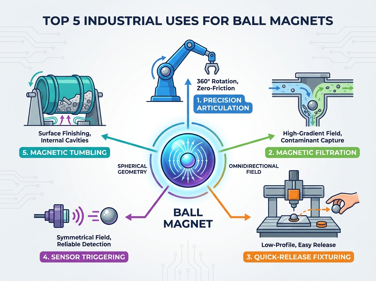
3. Quick-Release Fixturing and Workholding
Rapid manufacturing processes demand extreme speed. Laser cutting, CNC routing, and automated assembly rely on tight scheduling. Clamping and unclamping materials traditionally consumes valuable cycle time. Furthermore, hard mechanical clamps can easily warp delicate substrates. Overtightening a standard metal clamp permanently damages thin sheet metal or acrylic panels. Manufacturers need a faster, gentler way to secure parts.
You can use these spheres as low-profile, quick-release hold-downs. Their rounded shape allows operators to easily roll or tilt them off the work surface. This twisting motion cleanly breaks the magnetic circuit. Flat blocks, conversely, require significant prying force to remove. A quick roll action saves precious seconds during every single part changeover.
Evaluate your setup by looking at workflow efficiency. You should measure the exact time saved per cycle versus traditional mechanical clamps. You must also evaluate surface protection. Determine the risk of the hard metal scratching your delicate workpiece. Operators often place a thin polymer sheet between the sphere and the part to prevent scratching.
Implementation risks center heavily on physics. Because the contact area is only a single point, the actual holding force is significantly lower than the magnet's theoretical maximum pull strength. Engineers must calculate the exact number of spheres needed. You must secure the workpiece against aggressive lateral machining forces. If you use too few spheres, the CNC router bit will push the part out of alignment.
4. Sensor Triggering in Harsh Environments
Mechanical limit switches fail rapidly in environments filled with high dust, moisture, or intense vibration. Internal springs jam when exposed to factory grime. Standard flat magnets used for Hall-effect or reed switches present another challenge. They require strict directional alignment. This strict polarity requirement severely complicates installation on fast-moving assembly lines. A slight bump ruins the sensor alignment.
Deploying a sphere as the primary actuator solves this beautifully. The magnetic field remains perfectly symmetrical around the sphere's axis. Because of this, rotational misalignment during installation or operation does not degrade the sensor's ability to detect the field. You can drop it into a housing without verifying perfect orientation. The Hall-effect switch will read it consistently every time.
You must evaluate the field reach accurately. Ensure the sphere's size and grade project a sufficient magnetic field. Measure the Gauss rating at a distance. It must successfully trigger the sensor through required air gaps or heavy protective housings. You must also verify component compliance. Ensure your chosen materials meet strict RoHS and REACH standards for modern electronic components.
Beware of free movement within the housing. If the sphere rotates freely in its enclosure, the primary poles will shift direction. This shifting potentially causes erratic, unreliable sensor readings. You must fix it firmly in place. Use industrial adhesives or tight press-fits to lock the orientation permanently. This prevents the poles from wandering during heavy machine vibration.
5. Magnetic Tumbling and Surface Finishing
Deburring and polishing intricate machined parts is notoriously difficult. Non-ferrous materials like brass, aluminum, or intricate jewelry pose a unique challenge. Traditional vibratory tumblers often fail to reach deep blind holes. They cannot polish internal cavities effectively. Traditional media simply jams inside small crevices. This leaves the internal surfaces rough and unfinished.
Magnetic tumbling offers an elegant solution. It utilizes a rotating magnetic field to drive tiny stainless steel pins against the parts. Manufacturers often embed powerful spheres in the base drive-plate. Spinning this plate creates a rapidly shifting magnetic vortex. This vortex forces the micro-pins into every tiny cavity and blind hole. The result is a flawlessly polished internal surface.
Evaluation dimensions rely heavily on torque and power. The size and grade of the spheres directly dictate the required motor torque. They also determine the volume of parts you can process per batch. Furthermore, you must measure flux density. Higher N-grades, such as N50 or N52, provide much more aggressive finishing action. Stronger fields whip the pins much faster.
Be vigilant about thermal risks. High-speed rotation generates substantial eddy currents within the machine base. These currents create significant radiant heat. You must ensure the drive system has adequate cooling. Proper ventilation prevents the components from degrading due to thermal shock. Overheated neodymium quickly loses its permanent magnetic charge.
6. Sourcing and Evaluating Ball Magnets for Scale
You must apply strict shortlisting logic during procurement. Do not default to the highest available grade, like N52, unless absolutely required. You must balance your raw pull force requirements with real-world environmental constraints. High temperatures and excessive moisture dictate different material choices. An N52 grade degrades quickly in an 80°C engine bay.
Vendor evaluation requires rigorous auditing. Always request comprehensive magnetic testing reports from your supplier. You need to review the Demagnetization curves and B-H curves. These documents verify magnetic consistency across large batch orders. You must also audit the supplier’s coating thickness consistency. Spherical geometries are notoriously difficult to electroplate evenly. Thin spots in the plating will rust immediately.
Summary Table: Grade vs. Temperature Tolerance
| Neodymium Grade | Max Operating Temp (°C) | Relative Pull Force | Ideal Industrial Use Case |
| N42 (Standard) | 80°C | High | Room temperature fixturing |
| N42SH (High Temp) | 150°C | Moderate-High | Hot fluid filtration traps |
| N42UH (Ultra Temp) | 180°C | Moderate | Heavy motor applications |
Your immediate next-step actions should focus on validation. Procure a small sample batch first. You need to test point-contact durability under actual stress. Test the thermal stability in a real-world working prototype. Do this extensively before committing to large-scale volume manufacturing. Real-world testing reveals mechanical flaws that computer simulations easily miss.
Conclusion
- Evaluate operating temperatures carefully before selecting a specific magnetic grade.
- Always calculate the exact breakaway torque considering the limited point-contact surface area.
- Use specialized epoxy or PTFE coatings when deploying in wet or corrosive fluid environments.
- Secure actuators permanently with adhesives to prevent pole shifting in sensor arrays.
- Consult with a magnetic engineering specialist to model the circuit and request functional prototypes for operational testing.
FAQ
Q: Why is the pull force of a ball magnet lower than a disc magnet of the same volume?
A: Pull force relies heavily on the surface area in contact with the ferrous material. A ball magnet only has a single point of contact. This significantly reduces the friction and direct holding force compared to the wide, flat surface of a standard disc.
Q: Can ball magnets be axially or diametrically magnetized?
A: Yes. While the physical shape is a perfect sphere, the internal magnetic orientation is determined during the manufacturing process. Most industrial spheres are axially magnetized, meaning the distinct poles rest at opposite ends of a single theoretical axis.
Q: What is the best coating for a ball magnet in an industrial setting?
A: It depends entirely on the environment. NiCuNi (Nickel-Copper-Nickel) is standard for dry mechanical applications. Epoxy or PTFE is required for wet, corrosive, or fluid-filtration environments to prevent rapid oxidation.
Q: Are neodymium ball magnets prone to chipping?
A: Yes. Because they impact hard surfaces at a single tiny point, the localized stress is very high. They should not be allowed to snap together forcefully. The brittle sintered neodymium beneath the protective plating will easily crack or shatter under high-velocity impacts.